FEC Design and Layout: Zones, Flow and Sightlines
2026年11月5日 / By safekidsplay_admin
Quick Answer
A practical FEC design and layout should balance the anchor attraction, age-specific zones, customer circulation, queueing, parent areas, staff sightlines, support spaces, and maintenance access. Before placing equipment, buyers should verify usable area, clear height, columns, exits, building services, and the customer journey. The 2D layout should prove that the venue can function; the 3D design should then communicate theme and visual experience. Capacity should be reviewed against the actual layout and operating plan rather than estimated from floor area alone.
What Should Be Confirmed Before FEC Design?
Begin with the measured building plan and identify usable area, tenant boundaries, clear height, columns, beams, entrances, emergency exits, lighting, HVAC, sprinklers, and other fixed services. Include loading and access constraints because large equipment may need a planned route into the venue.
Confirm target ages, core attraction, party or group functions, parent seating, operating model, staffing assumptions, budget, and opening date. These decisions determine how much area should be protected for activities and how much is needed for support and circulation.
How Should a Family Entertainment Center Be Divided Into Zones?
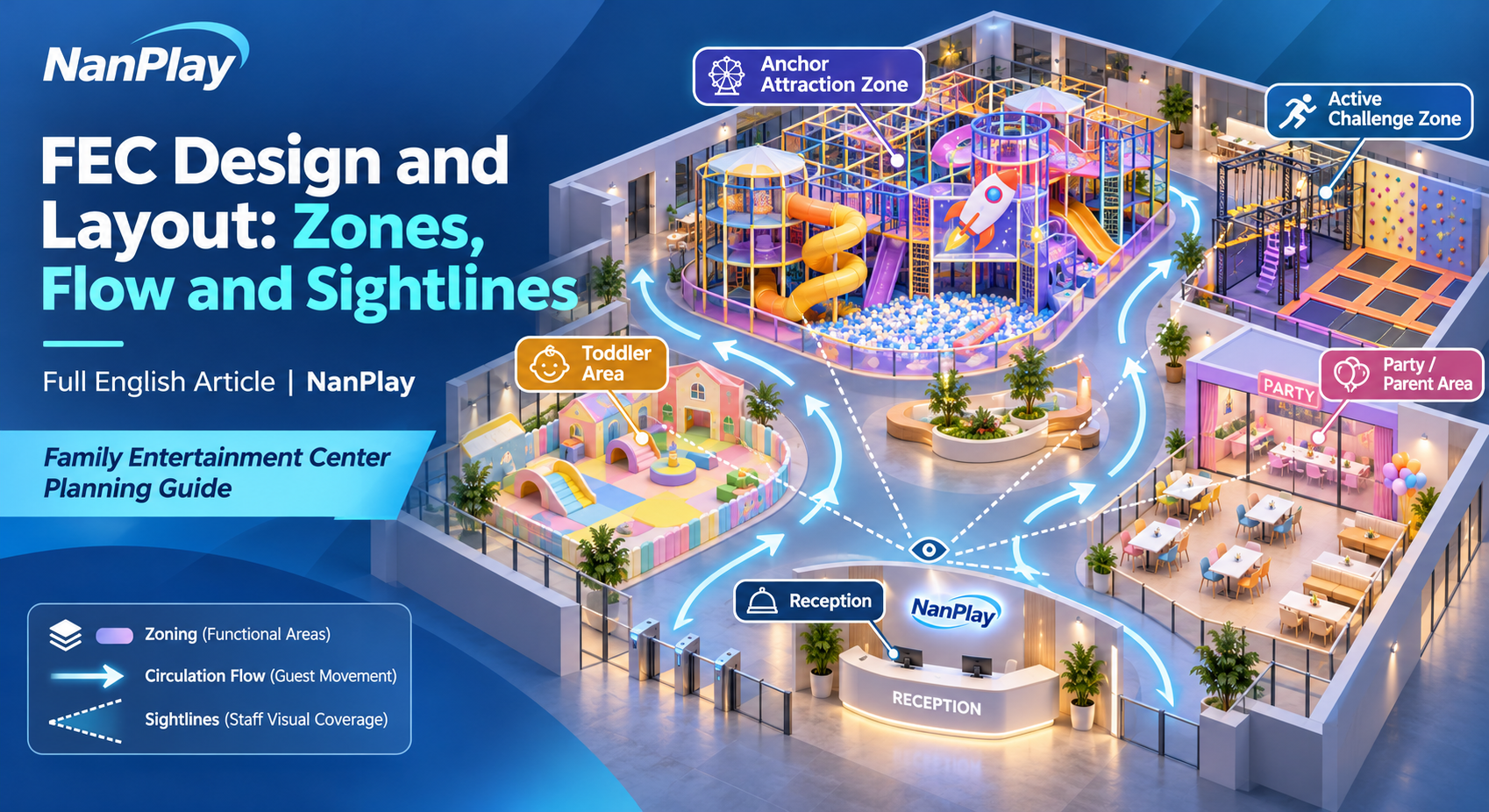
Create a hierarchy: one anchor attraction, supporting activity zones, and service or comfort functions. Depending on the concept, the anchor could be an indoor playground, trampoline zone, climbing or ninja challenge, or another activity that defines the venue. Toddler play, interactive features, party rooms, parent seating, reception, storage, and staff routes should be positioned around that core.
Zone boundaries should reflect age, intensity, supervision, and customer flow. A younger-child area should not be placed where fast-moving users cut through it. Party groups should have a clear path to their room and activity areas without disrupting ordinary visitors.
Where Should Family Entertainment Center Equipment Be Located?
Place equipment according to footprint, height, entry and exit points, expected queues, observation needs, and access for maintenance. High-visibility anchor attractions may benefit from a clear sightline from reception or main circulation, while support functions may be better located away from the busiest activity routes.
Do not position equipment only to create a visually balanced 3D image. The layout must show how users enter, use, and leave each attraction, how staff access the area, and how replacement components can be brought in without unnecessary disruption.
How Should Commercial Playground Equipment Fit the Layout?
Each item should be checked against the floor plan and equipment schedule. Confirm its footprint, height, interfaces with neighboring zones, any relevant clearances, and the location of access points. If an attraction needs a queue, landing zone, orientation point, or staff position, include that area explicitly.
Use consistent identifiers across the 2D plan, 3D design, quotation, and equipment schedule. This makes it easier to identify discrepancies before production. If the buyer asks for a design change, update all connected documents rather than relying on a verbal explanation or a revised rendering alone.
How Should Customer Flow Be Designed?
Plan circulation from entry to check-in, activity zones, parent areas, party functions, support facilities, and exit. Identify pinch points where queues, shoes, strollers, or group arrivals could block movement. Maintain clear routes to exits and avoid making staff cross active play areas repeatedly to reach storage or service areas.
Customer flow should be checked under different operating conditions: normal walk-in traffic, party arrivals, school or group visits, and closing periods. The right layout depends on how the venue will actually be used, not only on an empty-floor drawing.
How Do Ceiling Height and Columns Affect FEC Design?
Clear height can limit multi-level structures, slides, climbing features, trampoline or challenge attractions, and overhead decoration. Columns may split the available footprint or interrupt sightlines. Fixed services such as ducts, lights, and sprinklers can also affect placement and installation.
Mark these constraints on the 2D plan before attraction selection is finalized. If a column must be integrated into the design, verify the proposed interface and circulation around it. Local professionals should confirm building and fire requirements; equipment planning should work from the verified information.
How Should Capacity and Staff Sightlines Be Planned?
Capacity should not be inferred from total square meters alone. It depends on attraction design, usable activity space, movement routes, age mix, operating rules, supervision, and applicable local requirements. Buyers should ask the project team to explain the assumptions used for any proposed capacity.
Mark staff observation points and test what can be seen from each position. Check entrances, toddler areas, elevated play, transitions, and attractions that require more direct supervision. The final staffing model should match the sightlines and the actual operating procedure.
How Does a 2D Layout Become a 3D Commercial Indoor Playground Design?
The 2D plan establishes dimensions, zones, flow, equipment positions, exits, and operating relationships. The 3D design then communicates theme, colors, decorative elements, scale, and the intended visual experience. The two should be developed together but approved for different purposes.
Before manufacturing, connect the approved design to written specifications and a final equipment list. Confirm what is included, which elements are custom, how materials and colors are recorded, and who approves later changes. The design is ready for production only when the commercial scope and visual concept are aligned.
Decision Table: What Buyers Should Compare
| Zone or Function | Layout Priority | Review Question |
| Anchor attraction | Visibility and clear approach | Can visitors understand where the main activity begins? |
| Toddler area | Lower-intensity activity and observation | Can parents and staff see the area clearly? |
| Active/challenge zone | Flow, supervision and access | Are queues and transitions controlled? |
| Party and parent functions | Arrival, waiting and service movement | Can groups move without blocking play or exits? |
| Service and circulation | Clear routes and maintenance access | Can staff reach equipment and exits during operation? |
What Information Should Buyers Prepare?
Prepare the destination country and city, venue type, dimensioned floor plan, usable area, clear height, columns, entrances and emergency exits, target age groups, preferred attractions, theme direction, budget range, installation preference, and planned opening date. For a more accurate review, also provide any landlord restrictions, site photos, and the current building or CAD drawings available.
Common Mistakes to Avoid
- Placing attractions before verifying height, columns, and fixed building services.
- Estimating capacity from floor area alone.
- Creating queues that block entry, circulation, or exits.
- Using 3D visuals without a dimensioned 2D layout.
- Failing to show staff observation points and maintenance access.
Frequently Asked Questions
How do you design an FEC layout?
Start with verified site constraints, define the anchor attraction and supporting zones, then test circulation, queues, sightlines, exits, and maintenance access.
How should an FEC be zoned?
Use the target audience and activity intensity to organize the anchor attraction, toddler or beginner zones, active play, party/parent functions, and support spaces.
How much space does FEC equipment need?
It depends on the selected equipment and required circulation, entry/exit, queue, supervision, and maintenance areas. Use the actual equipment schedule.
Can an FEC be designed around columns?
Often, but the columns must be measured and included in the layout from the beginning. Their effect on equipment placement and flow should be checked.
How should capacity be confirmed?
Use equipment-specific information, the real usable layout, operating procedures, and applicable local requirements rather than a generic area formula.
Commercial Buyer Checklist
- Measured site plan and clear height confirmed
- Anchor attraction and supporting zones defined
- Target ages and activity intensity considered
- Equipment footprints and access points plotted
- Queues and circulation routes reviewed
- Staff sightlines marked
- Capacity assumptions documented
- Columns and building services included
- 2D plan matches the 3D concept and quote
- Maintenance and exit access protected
Final Thoughts
FEC Design and Layout: Zones, Flow and Sightlines should be treated as a project decision supported by site data, written scope, and realistic operating assumptions. NanPlay recommends connecting design, equipment specifications, delivery responsibilities, and maintenance planning before the project is released for production.
Project CTA
Send the measured floor plan, clear height, columns, entrances and exits, target users, preferred attractions, party/parent functions, and budget range for a layout discussion.
Reference: https://www.nanplay.com/family-entertainment-center/